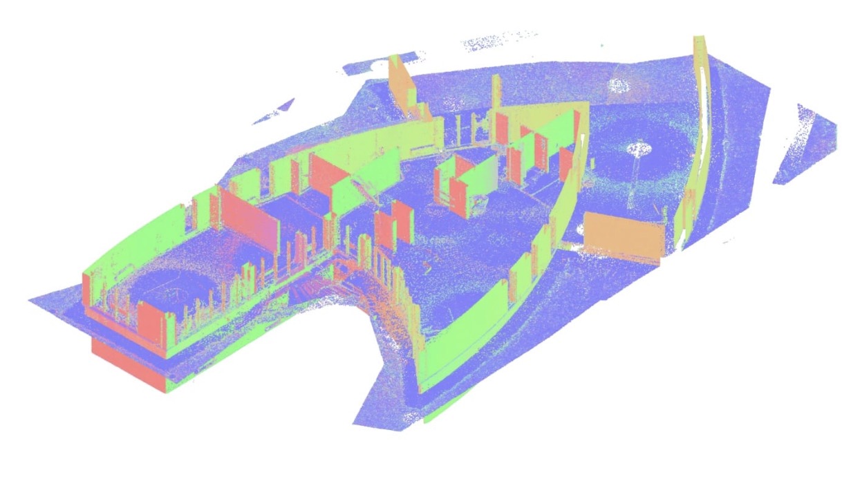
This article walks through that conversion step by step, from field capture to the final CAD or BIM deliverable, and explains where accuracy is gained or lost along the way.
Step 1: Planning the scan for the drawing you need
Good as-built drawings start before the scanner leaves the vehicle. The scope decides the scan density and the number of setups:
- Floor plans only need consistent coverage at roughly cut-plane height, plus door and window openings.
- Elevations and sections need clear lines of sight to facades, ceilings and roof structure.
- MEP documentation needs extra setups above ceilings and in plant rooms, where pipes and ducts hide each other.
A short call about the end use saves a return trip. If the client later asks for reflected ceiling plans and the ceilings were never scanned properly, no amount of office work will fix it.
Step 2: Capture and registration
On site, the scanner is moved from position to position so that every surface of interest is seen from at least one, ideally two, setups. Modern phase-based scanners record up to two million points per second, and a typical floor of an office building may take 30 to 80 setups.
Back in the office, the individual scans are registered into one coordinate system. This is the first quality gate. Registration reports show how well overlapping scans match; on a well-run project the overall result supports drawings with an accuracy of about ±2–3 mm. If the registration is weak, every line drawn later inherits the error.
When the project must tie into a survey grid or GIS dataset, control points measured with a total station or GNSS are added so that the point cloud sits in real-world coordinates rather than an arbitrary local system.
Step 3: Cleaning and segmenting the cloud
Raw clouds contain noise: people walking past, reflections in glass, furniture, parked cars. Before drafting, technicians remove what does not belong to the building and split the cloud into manageable pieces, usually by floor or zone. Horizontal slices at a fixed height become the basis for floor plans; vertical slices along grid lines become sections.
Step 4: Drafting the as-built drawings
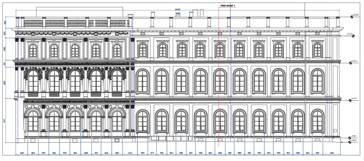
This is where the point cloud becomes a plan. Drafters trace walls, columns, openings, stairs and fixed equipment directly over the slices in AutoCAD, Revit or similar software. Two decisions matter most here:
- Level of detail. Does the client need every skirting board and pipe bracket, or clean architectural lines? Agreeing on a level of detail (often referenced as LOD 200–350 for BIM) keeps the drawings readable and the cost predictable.
- Real geometry versus idealized geometry. Old buildings are rarely square. Walls lean, floors slope and rooms are slightly trapezoidal. A good as-built drawing records these deviations instead of “straightening” them, because that is exactly the information designers and engineers need.
Specialist as-built drawing services typically deliver floor plans, elevations, sections and reflected ceiling plans in DWG, along with a Revit model when BIM is requested.
Step 5: Quality control against the cloud
Before delivery, the drawings are overlaid on the point cloud again. Checkers look for missed openings, misaligned walls and dimensions that do not match the data. Spot checks with tape or a laser distance meter on site are also common for critical dimensions.
Step 6: Delivery formats
Different users need different outputs:
| User | Typical deliverable |
| Architect | DWG plans, sections, elevations; Revit model |
| Structural or MEP engineer | Revit or IFC model, plus the point cloud for clash checks |
| Facility manager | PDF and DWG plans with room areas |
| GIS team | Georeferenced plans or footprints exported to the project coordinate system |
Keeping the registered point cloud alongside the drawings is worth it. When a question comes up months later, the answer is often already in the scan.
Where GIS and as-built documentation meet
For GIS professionals, building-level as-built data fills a gap between the site plan and the interior. Georeferenced floor plans let asset databases link rooms, equipment and maintenance records to accurate geometry. Campuses, airports and utilities increasingly ask for interior models that sit in the same coordinate system as their exterior GIS layers. Planning that requirement at the start, with control points measured during the scan, avoids expensive transformations later.
Common mistakes to avoid
- Skipping the scope conversation. The drawing list should be agreed before scanning.
- Ignoring registration quality. A good-looking cloud can still carry centimeter-level errors.
- Over-modeling. Modeling every bolt makes files heavy and slows down everyone who uses them.
- Throwing away the scan. The point cloud is the record of truth; archive it.
Conclusion
Laser scanning has made existing-conditions capture fast and precise, but the scan is only the first half of the job. The real deliverable is a set of as-built drawings that designers, contractors and owners can open, measure and trust. Understanding the steps between point cloud and plan helps project teams ask for the right scope, check the right things and get documentation that stays useful for the whole life of the building.